Software > Production, Procurement > Construction > Solid Edge Electrical Design
Electrical design software for ECAD/MCAD collaboration.

Solid Edge Electrical Design

Electrical design software for ECAD/MCAD collaboration.


Solid Edge Electrical Design - Electrical Design Software for ECAD/MCAD Collaboration

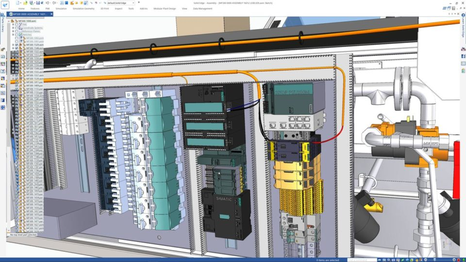
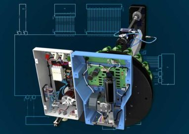
With Solid Edge Electrical Design, you can overcome the challenges of electromechanical design with software that is precisely tailored to this design area. Built on industry-leading technology from Mentor Graphics, the solution supports true design collaboration between the electrical and mechanical domains.

Advantages

  • make faster and more informed design decisions
  • validate designs with integrated electrical behavior
  • automate design processes to reduce manual tasks and improve efficiency
  • lower product costs through improved communication - Reduce need for expensive physical prototypes
  • improve service and maintenance documentation
  • productivity gains through unique sketch routing

Features (extract)

  • visualize the electrical aspects of your design in a 3D environment
  • design and simulate electrical systems, from simple electrical circuits to complex wiring harnesses
  • route wiring and place components in 3D assembly models
  • automate wire harness design to create production-ready drawings, bills of materials, calculations, NC files, and manufacturing reports
  • analyze your models to calculate the correct cable lengths and harness designs
  • use virtual simulations to ensure circuits perform to specification without waiting for physical prototypes
  • interactive collaboration between ECAD and MCAD disciplines - even in distributed locations
  • fully integrate PCB layout environment and mechanical design environment
  • built-in intelligent libraries for components, symbols and simulation models
  • connected mode with interactive cross-testing
  • wiring harness output to manufacturing
  • access to powerful libraries and parts repositories
  • bi-directional communication between electrical and mechanical environments
  • native 3D view for quick and easy component planning and placement
  • constraint-driven routing and tuning of high-speed networks
  • starter library with schematic symbols, PCB footprints and 3D models

Solid Edge Wiring Design

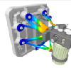
Solid Edge provides schematic features with unique built-in electrical analysis and simulation capabilities. Design teams can use Solid Edge to solve electromechanical design challenges earlier in the design cycle. Includes a starter library of more than 4000 common industrial parts. 

Solid Edge Harness Design

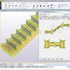
Solid Edge Harness Design includes harness layout and design tools that enable the creation of full-scale production-ready drawings, as well as the automated generation of bills of materials and reports.

Solid Edge Eletrical Routing

Solid Edge Eletrical Routing provides you with efficient features for creating, routing and structuring wires, cables and cable bundles in a mechanical assembly. Easily define a 3D path between parts and the properties of wires, cables, and bundles. Intuitive wizards help you assign electrical components and connectors with pre-configured Solid Edge parts. Export directly usable and cleaned-up list files to schematics. Wires are then assigned lengths and can be used for electrical analysis.

Solid Edge PCB Design

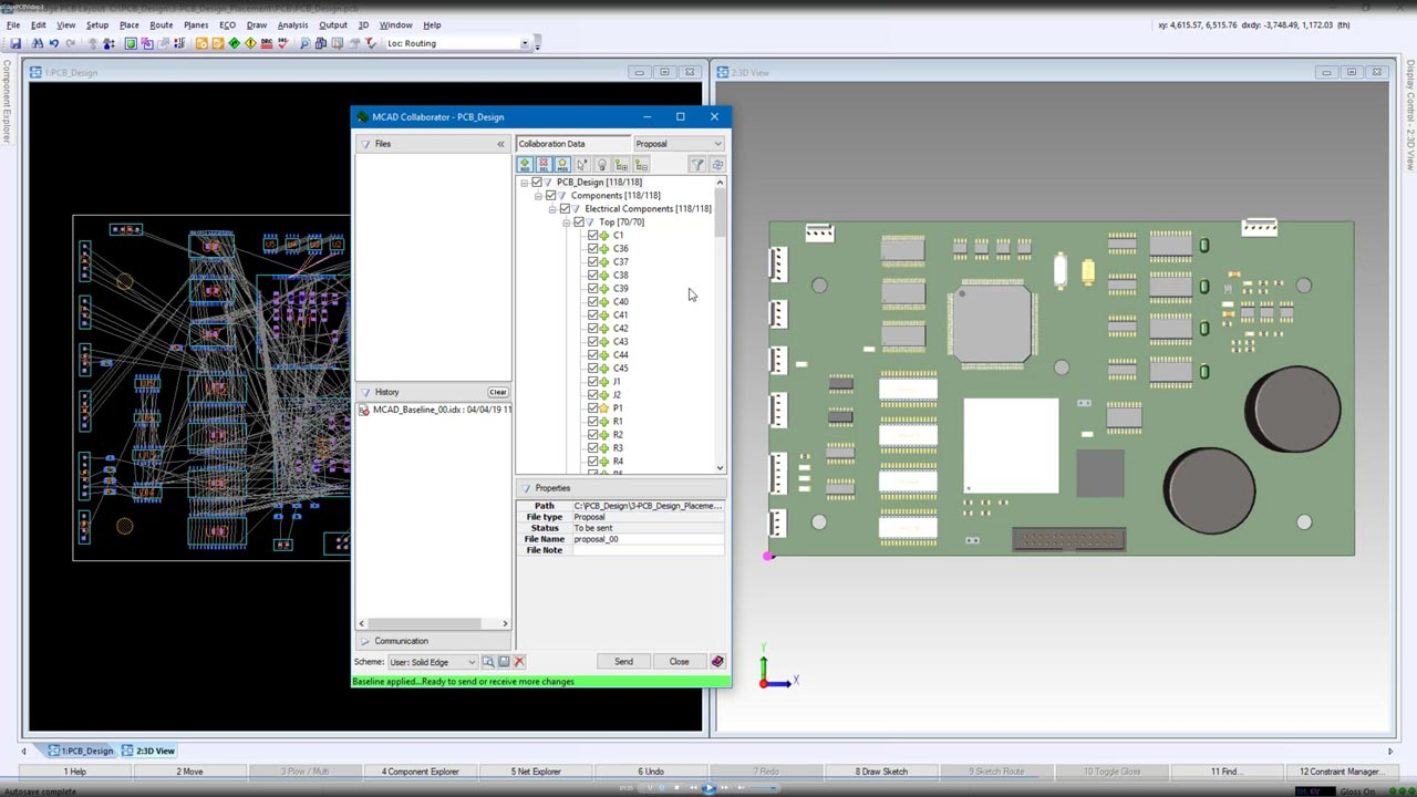
Simplify PCB design with Solid Edge PCB Design and schematic capture and PCB layout tools. The software includes dynamic routing, 2D/3D hierarchical design and placement, and ECAD/MCAD collaboration. Visualize problems in a 3D PCB environment. Benefit from automated placement planning and management.

Solid Edge PCB Collaboration

The software also clearly puts an emphasis on collaboration. With the help of the software, you overcome the communication barriers of PCB design.

Looking for the right software? Trust SoftGuide!

Our experts will find the perfect solution for you - independently and at the cutting edge of software trends.

Similar Software:

Functions (excerpt) of Solid Edge Electrical Design:

2D representation
3D representation
Analysis functions
Collaboration
Data exchange
DXF Format
Error tolerance
Graphical editing
Maintenance
Cable plan creation
Construction aids
Multilayer
Project Management
Circuit diagram creation
Switch cabinet and machine views
Simulation

Looking for the right software? Trust SoftGuide!

Technical specifications:

Web-based:
no
SaaS, Cloud:
no
Multi-user (network-compatible):
yes
Multi-client compatible:
no
Customizing:
possible for a fee
Vendor based in:
Germany
Dialogue language(s):
English, German, French
System requirements:
Compatible operating systems (runs with):
Win 11
Win 10
Win 8
Win 7
Win Server
Mainframe based
Unix based
Linux based
Mac OS
Mobile OSs (supports):
iOS
Android

Corresponding rubrics for Solid Edge Electrical Design:

Alternatives

Solid Edge Electrical Design
AUCOPLAN
3D Plant Design and Factory Planning Software | M4 PLANT
ANSYS Simplorer / Ansys TwinBuilder - System Simulation
Precast Software
Ansys
ANSYS Maxwell
ELITECAD 3D BIM Software
ELCAD
ANSYS CFD (CFX and FLUENT)
ATHENA - CAD Software for metal construction
cadvilla house planning software (CAD for architecture)
EPLAN Harness proD
Sheet CAD
EPLAN Engineering Configuration
visTABLE®
shortinfo
Electrical design software for ECAD/MCAD collaboration.
High-end engineering system for planning, operation and maintenance of I&C-technical plant
3D CAD software for plant engineering and factory planning
ANSYS Simplorer - Software for System Simulation
Technical processing of precast concrete elements under AutoCAD
The leading simulation software for development and design.
Software for 2D and 3D simulation of electromagnetic fields
model-oriented and parametric 3D CAD software (BIM)
CAD/CAE system for electrical engineering, hydraulics, pneumatics
CFD software, software for numerical flow calculations (flow simulation) with CHT
CAD software for curtain wall and shopfront design
cadvilla - State-of-the-art architecture software for planning and design
Construction and documentation of wire harnesses and nail board drawings
over 240 unwindings, 3 D representation, puzzle, nesting, folds, dimensioning, DXF
The basis for functional engineering
Factory planning software with intuitive usability and methodical support
Multi-user (network-compatible)
yes
yes
yes
yes
yes
yes
yes
yes
yes
yes
yes
no
yes
yes
yes
yes
Multi-client compatible
no
yes
yes
yes
yes
yes
yes
yes
yes
yes
no
no
yes
yes
yes
no
Compatible with


Interfaces
3D PDF
BIM
DWG
DXF
FBX
HSF
IFC
IGES
PDF
STEP
STL
VRML
DWG
DXF
IFC
PDF
SketchUp
STL
Other requirements for soft- and hardware
Memory: 8 GB RAM Hard disk: 3 GB Graphics Card: 3D compatible graphics card DirectX 10.1+ compatible 1GB or higher Screen resolution Recommended: 1920 x 1080 pixels (Min. 1400 x 900 pixels)
64 bit version available
Same like Autocad, Trademark of Autodesk Inc.
Screen resolution from 1024x768 pixels
Dialogue language(s)
English, German, French
English, German
English, German, French
English, German
English, German, French
English, German
English
English, German, French
English, German
English, German
English, German, French
English, German, Spanish, French, Hungarian, Italian, Dutch, Polish, Portuguese, Russian, Slovak, Turkish
English, German, French
English, German
Documentation
Manual
Online Help
Demo version
Technical documentation
Manual
Online Help
Demo version
Technical documentation
Manual
Online Help
Demo version
Technical documentation
Manual
Online Help
Demo version
Technical documentation
Manual
Online Help
Demo version
Technical documentation
Manual
Online Help
Demo version
Technical documentation
Manual
Online Help
Demo version
Technical documentation
Manual
Online Help
Demo version
Technical documentation
Manual
Online Help
Demo version
Technical documentation
Manual
Online Help
Demo version
Technical documentation
Manual
Online Help
Demo version
Technical documentation
Manual
Online Help
Demo version
Technical documentation
Manual
Online Help
Demo version
Technical documentation
Manual
Online Help
Demo version
Technical documentation
Manual
Online Help
Demo version
Technical documentation
Manual
Online Help
Demo version
Technical documentation
number of installations
2000
800
k.A.
>500
22000
> 16.000
zwischen 250 und 300
First installation (year)
2000
1970
1990
1985
1989
2011
2011
1985
2005
Functions
16/16
13/16
13/16
12/16
11/16
11/16
10/16
9/16
9/16
8/16
7/16
7/16
7/16
6/16
6/16
6/16
Compare other alternatives to Solid Edge Electrical Design