Sheet CAD
over 240 unwindings, 3 D representation, puzzle, nesting, folds, dimensioning, DXFVersion: 16.4.2
Updated on 18. Feb 2026 by SoftGuide
Version: 16.4.2
Was ist Sheet CAD?
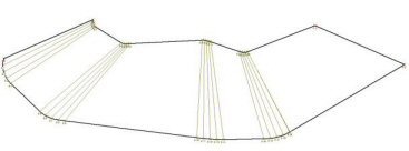
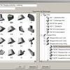
With Sheet CAD, more than 240 different types of sheet metal coils can be processed, such as tanks, transition pieces, ventilation ducts, silos, pipe elbows, pipe branches, screw conveyors, etc. The desired case is selected from the selection menu (Fig. 1) and the dimensions are entered directly (Fig. 2). Then you get the scaled three-dimensional figure on the screen - for the first visual check. The full-scale development is called up by mouse click.
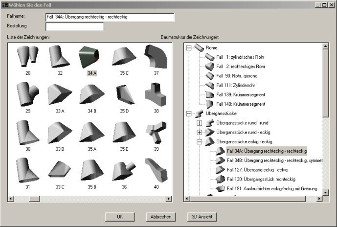 |
| Abb. 1: Selection menu |
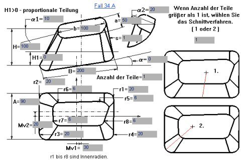 |
| Abb. 2: Construction drawing for entering the dimensions |
Likewise, the unwindings can be plotted out as a jigsaw puzzle on a scale of 1:1. Technical calculation values such as unwinding length and width, sheet dimensions, sheet weights, cut and weld seam lengths, etc. can be printed out in a table for each case or transferred to EXCEL
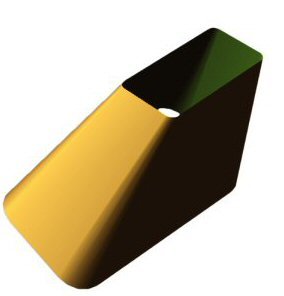 |
| Abb. 3: full-scale, rotating 3D display |
When connecting an NC control, an arc-line interpolated data output is preferably selected: The contour then consists of basket arcs and straight lines. When reaming by hand, you can choose between x-y coordinates and a compass construction.
The products to be manufactured from raw sheet metal can then be conveniently produced from the two-dimensional unfolding with the aid of machining parameters such as bending lines, flame-cut allowances, folded edges, etc. The position of the weld seam can then be determined. The position of the weld seam can be set interactively (Figs. 4 and 5):
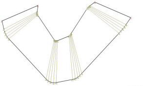 |
| Abb. 4: System proposal for the weld seam layer |
|
|
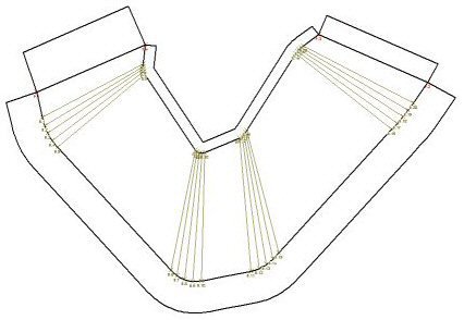
| Abb. 5: Identical figure after moving the weld seam |
In the case of large unwindings, these can be assembled as a puzzle from several small sheets. To do this, a mesh of sheet metal plates of a specified size is placed over the unwinding contour and moved with the mouse in such a way that optimum material utilization is achieved. Coordinates are then specified separately for each sheet.
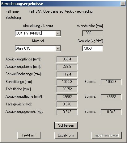 |
| Abb. 6: Calculation results |
The accuracy of the sheet unwinding is entered as a calculation tolerance in millimeters. A low specified accuracy decreases in particular the number of coordinates to be torn open.
Many parameters can be changed, making Sheet CAD very flexible and powerful. Here are some points:
With the Dimensioning module, any length, angle and curvature can be dimensioned. The Nesting module allows you to move and rotate sheet unwindings with the mouse in order to nest them in a given sheet.
The Labeling module can be used to label unwindings and export them as DXF files, as well as the contours and bending angles. Uniform or non-uniform fold edges can be generated for each contour of an unwinding case.
For the most important cases, spigots can alternatively be entered as "attached" or "pierced".
For frequently used cases, the bend angles for each bend line are given in a table.
 |
| Abb. 7: Folded edges |
FACE SHEET
is an integral part of the Sheet CAD and is used for the design, calculation, 3D representation and development of angular sheet metal bodies, such as cabinets, containers, housings, etc. The program contains 59 macros for different standard variants. However, the customer can also design new macros himself by mere sketching. The results are output for CAD systems in DXF format and on a printer or plotter.
The face sheet program transfers the developments to various modules of the Sheet CAD program, which opens the following possibilities:
After the start, a selection menu appears with the different macros as in Sheet CAD.
Project no.: 15/221
Tender until: finished
As an energy technology company, we are active in plant construction, tank construction and ... more